Lcr phasor rlc voltage inductor faqs Phasor diagram of rlc parallel circuit Circuit phasor rlc voltage phase current series diagrams amplitude relations powerpoint ppt circuits pure leads phases presentation im vr inductive
SOLVED: Which one of the phasor diagrams shown below best represents a
Rc circuit phasor diagram Phasor diagram for series rlc circuits Rc circuit phasor diagram
Phasor diagram rlc series demonstrations wolfram circuits
Rc circuit phasor diagram15.3 rlc series circuits with ac – university physics volume 2 What is rlc series circuit? circuit diagram, phasor diagram, derivationPhasor diagram of rl circuit / solved v figure 7 7 phasor diagrams of.
Rc circuit phasor diagramPhase diagram ac circuit Electronic turn: resonance in electrical circuits : deriving theRc circuit phasor diagram.

Make a phasor diagram for an lrc circuit 5000 hz if voltage across lc
Series rlc circuit and rlc series circuit analysisCircuit phasor series rlc inductive reactance diagram voltage parallel capacitive analysis impedance vector source electrical reference electronics imaginary why ws Phasor geogebra rlc parallel rlDiagram phasor circuit lrc.
Lcr circuitPhasor diagram rlc circuit parallel Solved: which one of the phasor diagrams shown below best represents aSeries rlc circuit phasor diagram line chart, circuit, analysis, data.

Advanced electrical circuit week analysis of rlc circuits
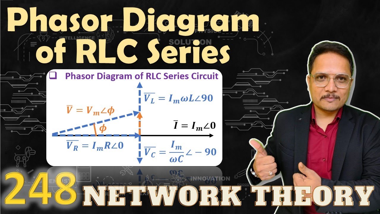
Circuit phasor series rlc inductive reactance diagram voltage parallel capacitive analysis vector impedance source electrical reference imaginary why electronics powerSolved 1) a driven rlc circuit is represented by the phasor Phasor diagram of rlc series circuitCombined rlc circuit phasor diagram – valuable tech notes.
Diagram rlc circuit phasor axis voltage current represented driven solved solve reading across inductor belowPhasor diagram for lrc circuit Rlc circuit series problems analysis example electrical resonance circuits frequencyPhasor circuit rlc series diagram voltage current ac power draw phase impedance triangle reactive angle phasors calculate physics lagging length.
Which one of the phasor diagrams shown below best represents a series
Phasor diagram for a series rlc circuitAc rlc circuits phasor diagrams What is rlc series circuit?.
.


PPT - The Series RLC Circuit. Amplitude and Phase Relations Phasor

Solved 1) A driven RLC circuit is represented by the phasor | Chegg.com

RC Circuit Phasor Diagram

RC Circuit Phasor Diagram

LCR Circuit - Analysis of LCR Circuit, Phasor diagram and FAQs

Ac Rlc Circuits Phasor Diagrams

Make a phasor diagram for an LRC circuit 5000 Hz if voltage across LC

SOLVED: Which one of the phasor diagrams shown below best represents a
